Featured Post

Introducing: The Meanest Looking Custom Built Skyline R34 GTR 1/7th Scale Remote Control RC Car

Passion, It's the thing that drives us to achieve. The push we feel to dare to dream something, ideal, and then manifest that vision into reality. For anyone who's ever fallen head over heels into an engine bay, or body work, or getting your car track ready, YOU KNOW that feeling that drives you to customize and make things as you feel they should be. Your intuition is second to none.  RC Car Skyline GTR R34 Custom Built Remote Control Car This GTR is no different from any of the other incredible cars featured on this site ( just look around; there's red ones , blue ones , silver ones , white ones , black ones ) - except for one, small, detail. - It's 1/7th the size! You wouldn't be able to fit inside it, but it still rips around like a GTR should, and is a whole lot of fun to drive I'm sure, and the customization on this build is phenomenal.  Nissan Skyline GTR RC Car Rear End Spotted on the RC sub, user XJuggernaut101 shared their build story with us of ho...

Battery Relocation to the trunk with new cables wires and ground

Battery relocation is a must for every enthusiast, when done correctly it helps to corner balance the car and moves weight lower to the ground and more over the rear axle for better handling. It also removes a lot of clutter from the engine bay, which makes for a much cleaner, safer and easier to work on engine. Pictured below is the kit that I'd ordered from Summit Racing. 
Battery Relocation box wires and kit
Summit Racing battery relocation kit
Some people move the battery to the back seat area, I had chosen to move it to the trunk. If you plan on tracking your car make sure you read the track rules, often when you relocate the battery there are some strict rules to follow about proper ventilation, and mounting.


With the old battery removed from the engine bay, unwrap the cable protectors and follow them to the harness, we want to move the positive and negative main connectors towards the frame rails, where they can both me secured easily.
Using stranded copper ground cable, I ran a ground wire from the trunk, under the car alongside the frame rail, where the brake lines are, using the HICAS line brackets to secure the line with tie-wraps. Following the frame rail right up into the engine bay, where I removed a small circle of paint to get down to the bare metal. Then, using a large bolt and washer, I secured the new copper ground line to the metal frame directly and to the harness negative wire. If you have a grounding kit this is also an ideal way to mount the terminal for that.
Engine bay Battery relocation main hot lead wire connection
Positive and negative cables hooked up in engine bay
Some people will argue that running a full copper ground wire is redundant, and they would technically be correct. But for peace of mind, and the little work required, I decided I'd rather be redundant than stuck on the roadside somewhere trying to figure out which ground has come loose.


As for the positive cable, I used a 0 gauge cable, connected it to the positive terminal on the harness in the engine bay. Remember to cover any exposed conductor with electrical tape to prevent shorting out. From the engine bay the wire was pushed through a hole in the firewall where the other harness comes through, near the  drivers' side kick panel. From there, the positive lead runs under the carpet along the frame of the car, under the back seats and directly into the trunk through the rear firewall. Where as the negative cable had to be pushed up through a grommet above the gas tank to get it into the trunk.
Battery box relocation to trunk
Positive and negative leads in the trunk
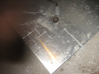
Cutting sheet aluminum metalAt this point you may choose to follow your own design, but I wanted to make a sort of electrical panel in the trunk, as I would need access to power later down the road to re-wire a new fuel pump and this will save me running wires front to back a second time. I'd also picked up a 200 amp circuit breaker and a Stinger voltage display, so I would need a way to mount these. If you can't find a circuit breaker you can use a 200 amp fuse, but if the fuse ever blows you'll have no way to reset the power system, again leaving stranded roadside.


Battery Circuit Breaker Fuse SwitchSo I started by cutting up some sheet metal. Then bending it into a shape the would allow me to neatly mount the circuit breaker and the voltage display, along with providing a solid mount for the battery. I wanted to mount the battery as low as possible, in the space for the spare wheel, but seeing as the gas tank was just under-neath, I didn't feel too comfortable drilling holes above it, not knowing how much of a gap there would be before the drill would hit the tank.


Everything was coming together nicely, and I mounted the battery box to the sheet metal using the provided hardware for the kit. Remember to measure the size of your battery as you don't want to get the tie-down post spacing wrong and have to tear everything apart just when you thought you were finished.


I secured the voltage display to the front of the panel, and the circuit breaker on the top. Then, quickly hooked the voltage display to test it out.
Battery Circuit Voltgae Display LED
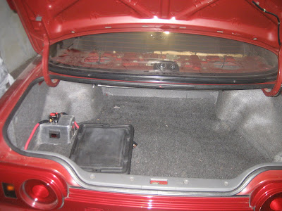
I secured the sheet metal panel and battery box to the passengers side of the trunk using 6 large bolts and some permanent Loctite. Then, dropped the battery in, and set up the wires. The positive cable ran along the back side of the trunk, underneath the carpet, around the edge and into the battery box from the side. The negative cable came out of the box heading towards the drivers' side, where it connect up with the copper ground wire, on a bolt that was fastened into the threaded hole in the middle of the spare wheel well that's usually used to secure the spare wheel in place. Lastly the NHRA required vent tube ran from the side of the box and to a hole through the body.
Red Top Battery Relocated to Trunk
Trimming the carpet to your specific set up will, help to keep the whole kit looking clean and proper. The photo below is the finished product.
Battery relocation with display panel

Comments

Anonymous said…
Hello sir!
I was checking out battery relocation and its wiring diagram when I noticed Nissan FAST showed me a different kind of wire (sort of). See I know the positive terminal harness has sockets for the fusible links but how about the negative???

On the Nissan FAST diagram w/ part code 24080. The negative terminal wire shows some kind of branching out at the bottom with some kind of socket to it. What I have on the GT-R is just a straight wire that bolted/grounded on the body halfway and is bolted/grounded at the block on the end. Am I missing something here, do I have the correct wire? Or Did I just interpret the FAST wrong? Hope to hear from you good guru out there.

Thanks! :)
J L said…
I believe you may be referring to the symbol for a Ground connection on a wiring diagram. Google ground connection, see if it looks like that.
Anonymous said…
So I have the correct negative terminal wire then? Its just a straight black yellow wire that is bolted on the body and block w/ NO socket or plug whatsoever?

Thanks for the reply sky!
Anonymous said…
http://www.beam-wiki.org/w/images/7/7a/Ground_Symbols.GIF